The CAN Device block allows you to define custom J1939 formatted receive and transmit messages. This tutorial will demonstrate how to use this function block.
CAN Device Function Block
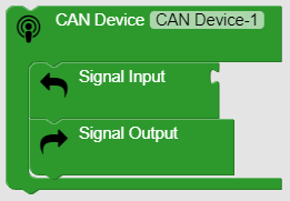
- Signal Input -
 variables received from the device
 - Signal Output -
 variables that will be transmitted to the device
 - Device - any piece of hardware on the CAN bus with a unique source address that can transmit and or receive J1939 formatted data.
- Sequence of variables in the list will be by order variables are created, they can be reordered by selecting and moving them.
Details Tab
- Source Address - This is the source address of the connected device. A message will only be received if it comes from the specified source address.
- Hover over the question mark icon for a description of other parameters.
Transmit Messages Tab
- These are the messages the device will transmit to the uControl Controller.
- Define the PGN and variables for the messages which will be considered signal inputs.
 Expands the list of variables for each PGN.
 The + symbols are used to add new PGN's or new variables.
 The PG Length will display how many bytes have been allocated, this must match the number of bytes the device will be transmitting. A mismatch will result in an error.
 The tool icon next to a PGN or a Variable will display a pop up window with additional parameters to set.
- Multiplexed Messages - The PG tool icon will display the filter settings for this PGN if needed for a Multiplexed message. Discriminator setting allows selecting any variable the user has defined to be used as the message id filter. The Discriminator Value is a numeric value that the message id variable in a incoming message must match.
Receive Messages Tab
- These are messages the uControl Controller will transmit to the device.
- Navigation and building messages is the same as on the Transmit tab.
- Transmit Trigger - Sets the transmit parameters for each PG. Each PG has its own setting. Select Tool Icon to access this setting. There are three trigger options available.
-
-
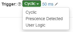
- Cyclic - repeats continually at the rate selected
- Presence Detected - One shot message at power up, wakeup from sleep, or watchdog reset if device is detected on the bus. Used to configure devices at power up.
- User Logic - Triggered when user created logic is true - be careful using this option else the message could be transmitted every logic cycle of 10-20mSec.
-
-
Useful Tips
- Duplicate Node -
 If you have sequentially ordered variables with a numeric suffix like Analog 1, Analog 2, Ace will automatically populate the next variable in order when you select the the duplicate button and fill in the Start Byte/Start Bit/Length as appropriate.
 - Recalculate Position -
 If you have a series of variables entered for a PG that are in sequential order but forgot one, you can add it at the end, drag it into the correct position, then select Recalculate, all the Start Byte/Bit information will be automatically recalculated in the new order.
Comments
0 comments
Please sign in to leave a comment.