The RS485 Serial Port Application is designed to communicate with external devices using MODBUS protocol either as a RTU Master, RTU Slave or to drive our line of PVA Gauges.
The examples in this Tutorial demonstrate both a RTU master and RTU slave configurations where the master is polling data from the slave and writing to its registers. There is an example of driving PVA gauges linked below.
Driving PVA Gauges
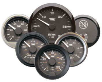
Note: To design a more redundant system we recommend using the PVCAN line of gauges which operate directly off of the CAN bus. PVA Gauge Backlight control is not available.
Step 1: Serial Port Setup
Select PVA Gauges , all parameters will be defaulted to the required settings.
Step 2: Driving Gauges
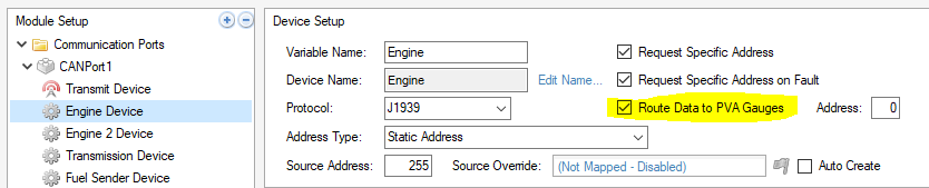
The application will automatically route data coming from a CAN port J1939 device to the PVA gauges.
To select which Device is used, select the "Route Data to PVA Gauges" checkbox. Any J1939 SPN associated with a connected gauge will be routed to it by the application.
Download the PVA Gauge Example
Driving a PVAA Alarm Gauge
To implement the PVAA Alarm Gauge all that is required is to set the DM1.LampStatus system variable with the proper value.
DM1.LampStatus Values:
0 = No Lamp = No Tone
1 = Amber Lamp = Intermittent Tone
2 = Red Lamp = Constant Tone
The DM1 Diagnostic Messages app will automatically set the lamp status as DM1 messages are received over the CAN bus. If there are any internally generated alarm conditions you manually have to set the lamp status variable.
The serial port must be configured for PVA Gauges and the gauge must be plugged in when the display powers up.
Download the PVAA Alarm Gauge Example
MODBUS RTU Communications
The display can be configured to function in either RTU Slave mode or in Master mode. There are two example configurations that explain each of these ways to setup the displays MODBUS serial port.
Download the MODBUS Master Example
Download the MODBUS Slave Example
Setting up a RTU Slave Device
- Step 1: In the Connections tab set Serial Port RTU Slave mode
- Step 2: Select baud rate and parity
- Step 3: Assign Slave address
- Step 4: Map Registers
Setting up a RTU Master Device
- Step 1: In the Connections tab set Serial Port RTU Master mode
- Step 2: Select baud rate and parity
- Step 3: Assign address of the slave device to be polled
- Step 4: Map Read registers - set direction to read and enable polling at desired interval
- Step 5: Map write registers - set direction to write and enable writing(polling) at desired update rate
- Step 6: Create additional slave devices as needed
Comments
0 comments
Please sign in to leave a comment.