This article will show you how to add a New Resistive Input Type to the PV380-R2 MSTD configuration. Start with the PV80 R2 template in version 2.9.23047. Previous ones are similar.
The PV380 menu system is complicated due to the ability to configure all the inputs and display. These instructions will help simplify making changes by bypassing the ability of an operator to configure inputs from the menu and just hardcoding an input.
In this example we will hardcode Resistive Input #4 to Hydraulic Temperature and display this on the Gauge screen.
Setup The I/O
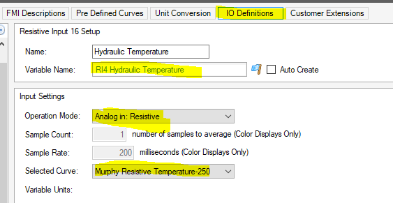
- Create a new variable called “RI4 Hydraulic Temperature” in the Input Settings folder. Set its units to degrees C to match the predefined sender curve we will be using.
- Create a new IO Definition called “Hydraulic Temperature” as a resistive input type and tie it to the desired resistive curve and the new variable you just created.
- Add the new I/O definition to the Hardware Input Resistive Input 4 in the connections tab and set it as the default. Don’t erase the existing definitions.
- The variable RI4 Hydraulic Temperature will now contain temperature data.
Display the New Variable
Option A - use an existing gauge like fuel economy on the main screen, this is under the DEF Gauge and under the Desired Speed Gauge can only be used when SCR and TSC1 is de-selected in the menu to hide them.
- In the page designer open Gauge Screen->Elect then open container CW Elect 1
- Select Smart Text Widget STG Fuel Econ
- Replace the 3 variables in the list with RI4 Hydraulic Temp by clicking on the variable name and selecting the new on from the drop down list.
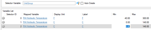
- Set the Units and Scaling for each of the three. Scaling should match the senders useable range.
- Select The Text Widget Fuel Economy and change the text for the heading to HYD TEMP.
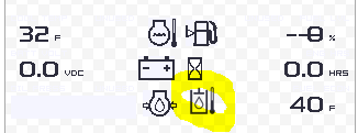
- Add a image widget and select the Hydraulic Oil Temperature Icon from the Library and place it next to the text gauge.
Option B - use a user menu selectable gauge on the second gauge screen.
- In the Programming tab go to the FourUpR1 variable and add RI4 Hydraulic Temp to the enumerated list. This will be item 62.
- Change the default setting of the variable View1Right1GaugeIndex to 62 so hydraulic temp becomes the default selection for that gauge. Do the same for View2Right1GaugeIndex and View2Right1GaugeIndex.
- In the Page Designer tab go to Gauge Screen-> Elect -> CW Elect2 -> CW Elect2 container. Select STG US STD R1-> Edit Smart Gauges and add item 62 RI4 Hydraulic Temp. Repeat the same process for the other two R1 gauges.
Modify the Menu
The menu needs to be modified to prevent the operator from changing the default settings, this happens when the engine type is selected (mechanical/electrical) or in the input settings. To accomplish this we will remove the initialization of RI4 in the engine selection and prevent the operator from being able to select RI4 in the inputs menu.
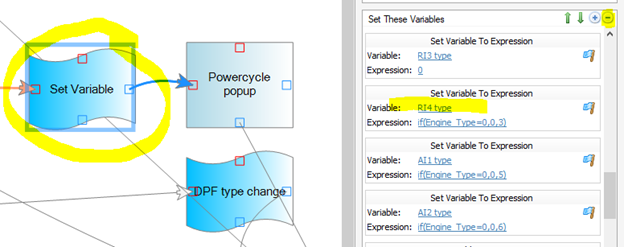
- Go to folder Engine Setup Menu Manager and select AP Engine Setup Button 5 Key Down. Look for “Set Variable” function box and delete Resistive Input 4.Msmnt Type and RI4 type from the list to prevent it from getting changed.
- Add code to skip over Resistive Input 4 (RI4) in the Input menu selection when IOMenuNextItem and IOMenuPrevItem are fired by a key press. To do this after each of these events are fired we need to call another events “Condition” and if RI4 has been selected we need to either go to the previous selection RI3 or the next selection AI1 depending on which direction the user is navigating. The variable IOMenuSelect contains the enumerated values for each menu item.
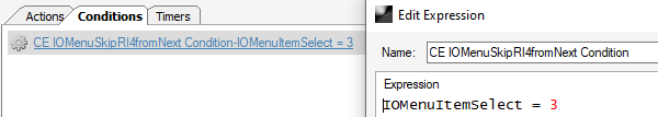
- Create a user event called IOMenuSkipRI4fromNext (called when moving towards next item)
- Add a conditional test to see if RI4 is selected
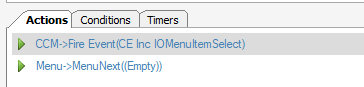
- Add actions that will fire if RI4 has been selected to move to the “next” item
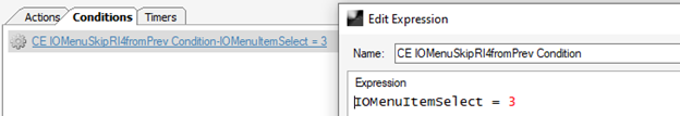
- Create a user event called IOMenuSkipRI4fromPrev (called when moving towards previous item)
- Create a Condition same as 2) above
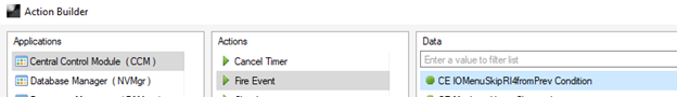
- Now we need to call these new events “condition” check and if they are true will fire and skip over RI4.
- Open user event IOMenuNextItem and add the following action
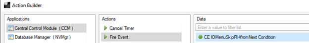
- Open user event IOMenuPrevItem and add the following action
Add Safety Alerts
Lastly add a new safety alert to display a pop-up message and illuminate the amber and red lamps when the temperature is too high.
- Create two new variables for the warning and shutdown temperature limits in the Shutdown Setpoints folder. Call them HydTempWarningPoint and HydTempShutdownPoint
- Set the default limits for each one in degrees C to match the RI4 units.
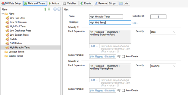
- In the Diagnostic Messages App “alerts & Timers” tab, add a new alert for High Hydraulic Temperature.
- Type in the desired message to display on the screen when there is an alert “High Hyd Temp”
- For severity level 1, create an expression that checks to see if the hydraulic temperature is greater than the shutdown set point then select a Severity level of Stop.
- For severity level 2, create an expression that checks to see if the hydraulic temperature is greater than the warning set point then select a Severity level of Warning.
- If additional logic is needed for example only show the fault messages when the engine is running simply add it to the expressions.
Comments
0 comments
Please sign in to leave a comment.