Download PV780 2.9.23044 Engine Simulator configuration here.
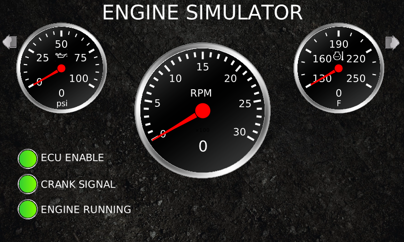
This PowerVision configuration for a PV780 simulates an electronic engines ECU allowing you to test features in your display or controller like auto start/stop sequences and auto throttling of various types. The display automatically responds to start commands and throttle commands outputting J1939 data for engine RPM, oil pressure, coolant temp, and a whole host of user selectable parameters. The configuration will respond to T4 regen messaging for various types of engines and has the capability of sending DM1 messages and lamp codes.
This configuration is provided as a starting point to help in your testing and is not intended to be an all inclusive test to validate every aspect of the end product. It is up to the developer to formulate a complete validation test plan which should include testing on the intended application. Feel free to modify this configuration to meet your specific needs or preferences.
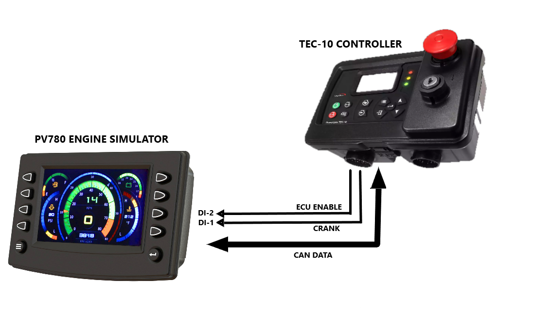
Hardware Connections:
- PV780 DI-1: Crank Input
- PV780 DI-2: ECU Enable
- PV780 DI-3: Preheat Input
- PV780 DI-4: Throttle Inc
- PV780 DI-5: Throttle Dec
- PV780 AI-1: 0-5Vdc Analog Throttle Input
- PV780 CAN-1: J1939 CAN Data Interface
Typical Connections using J1939-TSC1 Throttling
Getting Started
Connect the digital inputs DI-1 & DI-2 to the display as well as the CAN network. To get the "engine" started first enable the ECU Enable input then the Crank input until the RPM ramps up to the crank disconnect default speed of 700. Engine speed will automatically respond to the type of throttle control selected in the throttling page and all J1939 messaging will now be active.
Navigation
Use the arrows on the top left and right buttons to scroll between the main pages. Sub pages can be accessed from bottom left and right buttons where applicable.
Pages
- Throttle Page: Navigate to the Throttle page and select the throttling method you are using then set the various parameters as needed. Pay attention the the TSC1 address if using that throttling option. Select the engine type from the parameter list which will enable certain features and presets.
- CAN Settings Page: On the CAN settings pages you can enable a whole host of parameters an ECU will normally broadcast with static values. This includes Tier 4 parameters. Use Scroll +/- button to select the parameters then the adj +/- to change its value. Press the enable button to enable that PGN to be broadcast. Use the next page button to view all four pages.
- DM1 Page: The DM1 page will allow you to send individual DM1 messages or an entire BAM multipack of 55 predefined fault codes. Fifty Five is the maximum number of rows in the DM1 list created by the system app. The menu options allow you to build all of the parameters in the DM1 message from lamp status to SPN/FMI. This utility will also respond to requests for DM2 fault codes and can send either a single message or a multipack of 55 parameters.
- TIER 4 Page: On the Tier 4 Page press the T4-Type button to select which engine to emulate in response to regen requests and any special messaging associated with emissions. If your engine is not in the list then the config can be easily modified to include it. On the second T4 page DPF inhibit messages can be sent for each of the items listed in PGN 64892. T4 Lamps can be forced on/off, a reference to each icon is shown on page two. HEST Lamp can be forced on/off independently. All of this functionality is controlled through script routines that are engine specific or general T4 and are located in the Engine Simulation Tier4 folder.
- IO Status Page: This screen will show you the status of all the I/O on the PV780. The frequency output is used to mimic a a speed sensor measuring engine RPM.